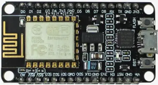
| Pin | Name | Function |
|---|---|---|
| 1 | A0 | Analog input (0-3.3V via onboard divider) |
| 2 | G | Ground |
| 3 | VU | VIN, 5V USB power input |
| 4 | S3 | Connected to onboard flash (SD3), avoid using |
| 5 | S2 | Connected to onboard flash (SD2), avoid using |
| 6 | S1 | Connected to onboard flash (SD1), avoid using |
| 7 | SC | Connected to onboard flash (CLK), avoid using |
| 8 | S0 | Connected to onboard flash (SD0), avoid using |
| 9 | SK | Connected to onboard flash (CMD), avoid using |
| 10 | G | Ground |
| 11 | 3V3 | 3.3V power output |
| 12 | EN | Chip enable |
| 13 | RST | Reset (active low) |
| 14 | G | Ground |
| 15 | VU | VIN, 5V USB power input (duplicate pin) |
| 16 | TX | GPIO1, UART0 TX |
| 17 | RX | GPIO3, UART0 RX |
| 18 | D8 | GPIO15, SPI CS, boot mode select |
| 19 | D7 | GPIO13, SPI MOSI |
| 20 | D6 | GPIO12, SPI MISO |
| 21 | D5 | GPIO14, SPI CLK |
| 22 | G | Ground |
| 23 | 3V3 | 3.3V power output |
| 24 | D4 | GPIO2, onboard LED, boot mode select |
| 25 | D3 | GPIO0, boot mode select |
| 26 | D2 | GPIO4, commonly used as I2C SDA |
| 27 | D1 | GPIO5, commonly used as I2C SCL |
| 28 | D0 | GPIO16, wake from deep sleep, no PWM/interrupt |
| 29 | G | Ground |
| 30 | VU | VIN, 5V USB power input (duplicate pin) |
Summary
Cheap Wi-Fi microcontroller board built around the ESP8266 chip, the predecessor to the ESP32. No Bluetooth, fewer GPIO pins than an ESP32, but very popular for simple Wi-Fi projects. Full 30-pin layout below is the common Amica NodeMCU V1.0 board — power/ground pins repeat across the header, and the S1/S2/S3/SC/S0/SK flash pins can vary slightly by manufacturer, so check against your specific board.
- MCU: ESP8266, single-core, 80/160MHz
- Wireless: Wi-Fi 802.11 b/g/n only (no Bluetooth)
- Flash: 4MB (typical)
- Usable GPIO: ~11 pins
- Supply voltage: 5V via VIN (USB), 3.3V logic