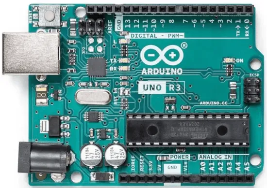
| Pin | Name | Function |
|---|---|---|
| 1 | VIN | Unregulated power input |
| 2 | GND | Ground |
| 3 | 5V | Regulated 5V output |
| 4 | 3V3 | Regulated 3.3V output |
| 5 | RESET | Reset (active low) |
| 6 | A0 | Analog input 0 |
| 7 | A1 | Analog input 1 |
| 8 | A2 | Analog input 2 |
| 9 | A3 | Analog input 3 |
| 10 | A4 (SDA) | Analog input 4 / I2C data |
| 11 | A5 (SCL) | Analog input 5 / I2C clock |
| 12 | AREF | Analog reference voltage |
| 13 | D0 (RX) | Digital I/O / UART receive |
| 14 | D1 (TX) | Digital I/O / UART transmit |
| 15 | D2 | Digital I/O, external interrupt |
| 16 | D3 (PWM) | Digital I/O, PWM |
| 17 | D4 | Digital I/O |
| 18 | D5 (PWM) | Digital I/O, PWM |
| 19 | D6 (PWM) | Digital I/O, PWM |
| 20 | D7 | Digital I/O |
| 21 | D8 | Digital I/O |
| 22 | D9 (PWM) | Digital I/O, PWM |
| 23 | D10 (PWM/SS) | Digital I/O, PWM, SPI chip select |
| 24 | D11 (PWM/MOSI) | Digital I/O, PWM, SPI data out |
| 25 | D12 (MISO) | Digital I/O, SPI data in |
| 26 | D13 (SCK) | Digital I/O, SPI clock, onboard LED |
Summary
The classic beginner microcontroller board, built around the ATmega328P chip. Simple, reliable, huge community support — the default choice for first electronics projects, though it has no built-in Wi-Fi/Bluetooth.
- MCU: ATmega328P, 16MHz
- Digital I/O: 14 pins (6 support PWM)
- Analog input: 6 pins (A0-A5)
- Flash memory: 32KB
- Operating voltage: 5V (recommended input 7-12V via VIN)