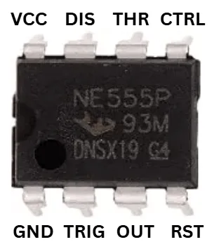
| Pin | Name | Function |
|---|---|---|
| 1 | GND | Ground |
| 2 | TRIGGER | Starts timing cycle when pulled low |
| 3 | OUTPUT | Timer output |
| 4 | RESET | Resets timer (active low) |
| 5 | CONTROL VOLTAGE | Adjusts threshold voltage (often left with a small capacitor to ground) |
| 6 | THRESHOLD | Ends timing cycle when voltage exceeds 2/3 VCC |
| 7 | DISCHARGE | Discharges timing capacitor |
| 8 | VCC | Power supply |
Summary
The classic 555 timer IC used to generate precise time delays or oscillating signals. — astable mode for repeating pulses (like blinking LEDs or tone generation), monostable mode for a single timed pulse. One of the most widely used ICs ever made.
- Supply voltage: 4.5V - 16V
- Package: DIP-8 / SOIC-8
- Modes: Astable, Monostable, Bistable
- Output current: Up to 200mA